Notice
This documentation is still in progress. Come help here!
Network
This section documents the network and its nodes.
IP Standard
The mesh runs a dual stack IPv4 and IPv6 networking. Each device is be assigned a minimum of 2 IP addresses, one of each type.
IPv4 Subnet CIDR
For IPv4 the following CIDR definition
- /32 - Single Host
- /30 - PtP L2TP etc
- /29 - PtP Antenna links where antennas are in bridge mode but require an IP for administration
- /24 - Antenna Subnets
IPv6 Subnet CIDR
For IPv6 the following CIDR definition
- /128 - Single Host
- /127 - PtP L2TP etc
- /126 - PtP Antenna links where antennas are in bridge mode but require an IP for administration
- /64 - Antenna Subnets
Backhaul network
Used for super nodes and core infrastructure
IPv4 range: 100.64.0.0/10
Address:   100.64.0.0            01100100.01 000000.00000000.00000000
Netmask:   255.192.0.0 = 10      11111111.11 000000.00000000.00000000
Wildcard:  0.63.255.255          00000000.00 111111.11111111.11111111
=>
Network:   100.64.0.0/10         01100100.01 000000.00000000.00000000 (Class A)
Broadcast: 100.127.255.255       01100100.01 111111.11111111.11111111
HostMin:   100.64.0.1            01100100.01 000000.00000000.00000001
HostMax:   100.127.255.254       01100100.01 111111.11111111.11111110
Hosts/Net: 4194302
IPv6: FD54:4f4d:5348::/48
Node Network
Used for community hubs and non-core devices
IPv4: 10.0.0.0/8 IPv6: FD74:6F6D:73:86::/48
Address:   10.0.0.0              00001010 .00000000.00000000.00000000
Netmask:   255.0.0.0 = 8         11111111 .00000000.00000000.00000000
Wildcard:  0.255.255.255         00000000 .11111111.11111111.11111111
=>
Network:   10.0.0.0/8            00001010 .00000000.00000000.00000000 (Class A)
Broadcast: 10.255.255.255        00001010 .11111111.11111111.11111111
HostMin:   10.0.0.1              00001010 .00000000.00000000.00000001
HostMax:   10.255.255.254        00001010 .11111111.11111111.11111110
Hosts/Net: 16777214              (Private Internet)
Fun Fact: IPv6 Address is in the fd::/8 range. The bytes of 74 6F 6D 73 86 converted into ASCII spell TOMSH (lower case for backhaul range)
Hostname Naming Standards
This is the decided upon official naming convention for all devices and SSID in the network
Supernode Name Standards
The supernode hostname is snXyY and where X is assigned by the Network Planning, Design and Operations working group, and yY is chosen by the node operator to identify network components within the node. For example a1 for antenna 1 and r1 for router 1.
All hostnames will be unique across the mesh.
The supernode devices will use the domain format operator.tcn.tomesh.net. A DNS and reverse DNS entry will be made for each device with such a domain name. For simplicity the devices will also carry an entry with the domain of tcn.tomesh.net
For example a FQDN (fully qualified domain name) will be sn1a1.core.tcn.tomesh.net for a device operated by the core team at Toronto Community Network. The node will also answer as sn1a1.tcn.tomesh.net
SSID
Public SSID
Public SSID will not extend the Babel protocol. They are standard access points connections for the users to access the mesh.
Format
tomesh.net
Mesh SSID
Mesh SSID are used to extend the mesh network. They have will have Babel running on them.
Format
tomesh-(protocol)-(meshid)
parameters
tomesh- is a constant and never changes
(protocol) is the protocol name the SSID is running. This could be for example airmaxac,80211s,adhoc
(meshid) optional, part of the string when SSIDs need to be isolated. PtP and PtMP antennas will use their hostnames
Example
A network node with hostname of sn1a1 running airmax-ac protocol would be
tomesh-airmaxac-sn1a1
A network node with running 80211s would be
tomesh-80211s
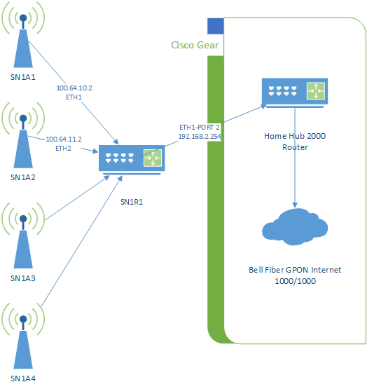
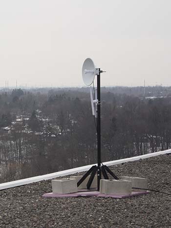
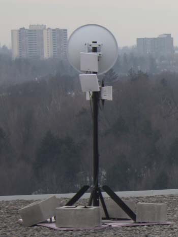
Supernode 1

Supernode 1 is located on top of 200 Woolner Ave, Toronto, alongside Cisco-deployed infrastructure belonging to the City of Toronto.
Network
The supernode consists of 4 antennas and a router. The router is connected to the Cisco switch which is connected to the Bell 2000 modem that offers internet access for use as a gateway path.
The router acts as a Babel routing device. The antennas are configured in bridge mode.
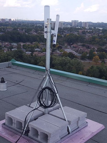
Hardware
Antenna 1
Antenna 1 is a Ubiquiti LAP-120 mounted on the west arm of the building, on the south side of the roof, colocated with Cisco on their mounts. The antenna is facing south.
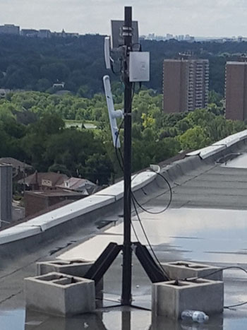
Antenna 2
Antenna 2 is a Ubiquiti LAP-120 mounted on the south arm of the building, on the east side of the roof, colocated with Cisco on their mounts. The antenna is facing east.
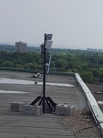
Antenna 3 and 4
Antenna 3 and 4 are Ubiquiti LAP-120 devices mounted on the north-east arm of the building. Antenna 3 is facing north-east and antenna 4 is facing north.
Router 1
Router 1 is a Ubiquiti EdgeRouter X-SFP mounted inside the Cisco cabinet in the ballast room. It is connected to the exit node over a L2TP tunnel using UDP.
Router is configured with a static IP and only routes to the exit node and a secondary VPS server. The secondary VPS is used to provide an OpenVPN tunnel for secure remote management of the device.
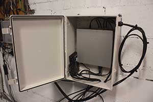
Physical Environment
The roof is accessible through ceiling hatches on the top floor of the building.

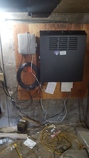
The router is installed in a black metal cabinet, located on the back wall of the ballast tank room on the roof. This room is accessible only from the roof. The entrance is on the east wall of the elevator hut. The doors are shorter than normal.
Network cables are run through a hole in the east wall.
Neighbourhood Testing
Testing was done at several points that had line-of-sight to the antenna. The antenna was hand-held, not tuned precisely. Results are for reference only, and do not necessarily represent what a permanent deployment could attain at that distance.
| Point | Distance (m) | Ping | Speed RX/TX (Mbps) | Signal (dBm) |
|---|---|---|---|---|
| a | 200 | 4.57 | 86/194 | -64 |
| b | 200 | 2.86 | 80/194 | -60 |
| c | 237 | 5.82 | 50/178 | -58 |
| d | 270 | 5.27 | 103/149 | -50 |
| e (1) | 396 | 5.11 | 83/172 | -58 |
| f | 2520 | 4.57 | 8.68/1.6 | -81 |
| f (2) | 2520 | 4.57 | 64.58/40.79 | -74 |
| g | 2660 | 82/123 | -62 | |
| g (3) | 2660 | 118/44 | -66 |
(1) Used both Nanostation AC (Loco5AC) and LiteBeam AC (LBE‑5AC‑23). Both performed the same.
(2) Second attempt done after correcting issue with sn1a2.
(3) Used Nanostation AC (Loco5AC) but could not adjust elevation.
Additional Notes
EdgeRouter X-SFP does not accelerate traffic over tunnels. Due to this, speeds are currently limited to around 400Mbps to exit node.
Supernode 4

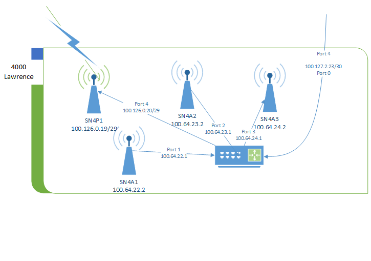
Supernode 4 is located on top of 4000 Lawrence Ave, Toronto, alongside Cisco-deployed infrastructure belonging to the City of Toronto.
Network
The supernode consists of 4 antennas and a router. The router is connected to the Cisco switch. The switch is connected via a city owned bridged Power Beam to 3434 Eglington Ave West that offers internet access for use as a gateway path.
The router acts as a Babel routing device. The antennas are configured in bridge mode.
Hardware
Antenna 1, 2 and Point to Point Antenna 1
Antenna 1 and 2 are Ubiquiti LAP-120 mounted on the north arm of the building, on the west side of the roof. Antenna 1 is facing south-west. Antenna 2 if facing north.
Point to Point Antenna 1 is a Ubiquiti PowerBeam AC Gen2 mounted on the north arm of the building, on the west side of the roof. The antenna is facing south-west pointing to 25 Cougar in Supernode 3.
Antenna 3
Antenna 3 is a Ubiquiti LAP-120 mounted on the south-east arm of the building, colocated with Cisco on their mount. The antenna if facing south-east.
Router 1
Router 1 is a Ubiquiti EdgeRouter X-SFP mounted inside the Cisco cabinet inside the main room on the roof. It is connected to the exit node over a L2TP tunnel using UDP.
Router is configured with a static IP and only routes to the exit node and a secondary VPS server. The secondary VPS is used to provide an OpenVPN tunnel for secure remote management of the device.
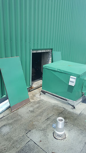
Physical Environment
The roof is accessible by using the stairs located on the east end of the building.
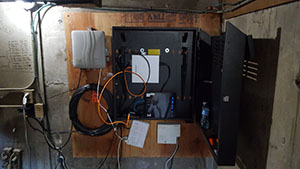
The router is installed in a white NEMA cabinet, located on the left wall of the roof top room. This room is accessible only from the roof across the walkway from the roof entrance.
Network cables are run through a hole in the south and north walls.
Additional Notes
- EdgeRouter X-SFP does not accelerate traffic over tunnels. Due to this, speeds are currently limited to around 400Mbps to exit node.
- Layer 2 point to point link over city owned power beam provides gateway exit traffic from 3434 Eglington ave.
Exit Node Configuration
Note: This is an advanced topic. If you are not familiar with the concepts in this document, please familiarize yourself with them first before proceeding.
Instructions are for installing an exit node on the Debian 10 operating system.
Babeld Installation
Install the latest version of babeld on the node. The latest version can be found currently at https://repo.tomesh.net/repos/apt/debian/pool/main/b/babeld/
Redistribute default gateway
Redistribute the default gateway to network, and prevent other exit node announcements from being accepted.
Create or append to the /etc/babeld.conf file
redistribute ip ::/0 le 64 metric 256
redistribute ip 0.0.0.0/0 le 24 metric 256
in ip 0.0.0.0/0 le 0 deny
in ip ::/0 le 0 deny
Enable NAT
Create /etc/rc.local and chmod +x it
Add the following content to the file
#!/bin/bash
ip6tables -t nat -F POSTROUTING
iptables -t nat -F POSTROUTING
ip6tables -t nat -A POSTROUTING -o eth0 -j MASQUERADE
iptables -t nat -A POSTROUTING -o eth0 -j MASQUERADE
exit 0
L2TP tunnels
Layer 2 tunneling protocol is used to allow gateways to connect over the internet to the exit node.
Server side scripts that support DDNS can be found in the toronto-community-network repository.
Babel
Babel is a loop-avoiding distance-vector routing protocol. It does link cost estimation and redistribution of routes from other routing protocols.
The network uses the reference implementation of Babel called babeld. Updated packages for Debian can be found at the Toronto Mesh Debian repository. These packages are compiled from source and packaged using scripts in the mesh-packages GitHub repository.
The package for the EdgeRouter X/SFP with UI support is managed by Toronto Mesh and can be found at https://github.com/tomeshnet/RouterX-Babeld-Package.
Prototype babeld configuration can be generated at http://node2.e-mesh.net/CONF/ for both OpenWRT and Linux.
When is Babel needed?
Babel is only required when your node routes IPs or a subnet that was not provided by a remote node.
Babeld console
Depending what port the service started on (local-port or -G options) you can access babeld's console using on of the following (assuming 999 is the port).
nc :: 999telnet :: 999
Note that some versions of nc do not support IPv6 so that command will not work.
Dump Command
The command dump in the console will list all the currently known data points of babeld.
add interface <INT> up true ipv6 <IPv6> ipv4 <IPv4>
Indicates that the interfaces <INT> will be used to find other babeld nodes. <IPv6> and <IPv4> are required for routing traffic through the nodes. If one is missing check your interface configuration.
add interface <INT> up false
Indicates the interfaces is assigned to babeld, but are currently not functional (cable not plugged in, or simply down)/
add neighbour f3ecb0 address <IPv6> if <INT> reach ffff ureach 0000 rxcost 96 txcost 96 cost
Indicates nodes found directly connected to babeld. <IPv6> is the local link IP found on the remote node, <INT> is the interface this link was found on. The combination of the two (<IPv6>%<INT>) is used to access the link.
add xroute...metric 256
Indicates the routes babeld is announcing from its routing table. metric 256 is the cost that it is announced as.
add route ...
Indicates routes that babeld has learned about in the network. installed yes or installed no indicates if this route is actively being used by being installed in the node's route table. Make note of metric numbers as they inform if the link will be used or not.
Hardware
This section documents the hardware used and tested for the network.
Hardware Benchmark
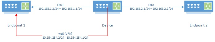
Lab setup
Device Device being tested
Endpoint1, Endpoint2 Devices not limited by CPU or network.
Instructions below are non-persistent. When device is restarted changes will be removed. wireguard package must be installed.
Device Lab Configuration
Configure interfaces
Configure the IP addresses on each interface
eth0 Interface on device connected to Endpoint 1
eth1 Interface on device connected to Endpoint 2
If the device has only one port, see Appendix A - Single Port Router to split the single port into two VLANs.
ifconfig eth0 NETMASK 255.255.255.0
ifconfig eth0 192.168.1.1 up

ifconfig eth1 NETMASK 255.255.255.0
ifconfig eth1 192.168.2.1 up
Note: You can add other IP addresses to an interface by using the ethx:x notation such as eth0:1. This can be used to add your home IP address alongside the lab's IP address and share the same switch
For example ifconfig eth0:1 192.168.10.1
Enable Routing
Most Linux distributions have routing disable. Enable it.
echo 1 > /proc/sys/net/ipv4/ip_forward
WireGuard
Configure a WireGuard server. Create a configuration file wg0.conf containing a private/public key.
NOTE: Do not use these keys in production!
cat <<"EOF"> wg0.conf
[Interface]
PrivateKey = 4LMdS6DPRe5gHcmMWYhZqlM9PzFTEeDz0kz0YIMCPm0=
ListenPort = 1000

[Peer]
PublicKey = //C9KkNgCgT/0+bIb6YMS558xNx6wJOwAuGbqO8CGlI=
AllowedIPs = 0.0.0.0/0
AllowedIPs = ::/0
EOF
Bring up the wg0 interface using above configuration
ifconfig wg0 down
ip link del dev wg0
ip link add dev wg0 type wireguard
wg setconf wg0 wg0.conf
ip addr add 10.254.254.1/24 dev wg0
ifconfig wg0 up
Endpoint1 Lab Configuration
Configure interfaces
Configure the IP addresses the interface. Make the default route the Device.
eth0 Interface on device connected to Device
ifconfig eth0 NETMASK 255.255.255.0
ifconfig eth0 192.168.1.2 up
ip route add 0.0.0.0/0 via 192.168.1.1
WireGuard
Configure a WireGuard client. Create a configuration file wg0.conf containing a private/public key.
NOTE: Do not use these keys in production!
cat <<"EOF"> wg0.conf
[Interface]
PrivateKey = cFP6gBOZrvqlt/XkdT7Cp6HOLuNMYa6yVNcCR+e9IEw=
ListenPort = 1000

[Peer]
PublicKey = 1510YjIH8EfQtJ2zxEEUb5+1B4HqmIv86pwpkJwNOW4=
AllowedIPs = 0.0.0.0/0
AllowedIPs = ::/0
Endpoint = 192.168.1.2:1000
EOF
Bring up the wg0 interface using above configuration.
ifconfig wg0 down
ip link del dev wg0
ip link add dev wg0 type wireguard
wg setconf wg0 wg0.conf
ip addr add 10.254.254.2/24 dev wg0
ifconfig wg0 up
Endpoint2 Lab Configuration
Configure interfaces
Configure the IP addresses the interface. Make the default route the Device.
eth0 Interface on device connected to Device
ifconfig eth0 NETMASK 255.255.255.0
ifconfig eth0 192.168.1.2 up
ip route add 0.0.0.0/0 via 192.168.2.1
Testing
iperf3 package must be installed. During iperf3 tests there are several things to remember:
-
iperf3, when run on device with low CPU resources, can consume CPU power to generate packets. Speed when transmitting will be slower than when receiving since the CPU will be taxed more
- using the
--repeating-payloadflag can reduce the stress placed on the CPU by not generating random data to transmit
- using the
-
CPU load can be seen by using the
topcommand during the test -
Watching
/proc/interruptscan also show where CPU cycles are being spent -
Some devices have hardware offloading that can increase performance when routing through the device
Interface speed
This will test the interface speed between the Device and Endpoint1.
On Endpoint1:
iperf3 -s
On Device:
-
Test Forward speed
iperf3 -c 192.168.1.2 -
Test Reverse speed
iperf3 -c 192.168.1.2 -R
WireGuard to WireGuard
This will test the interface speed over WireGuard.
On Endpoint1:
iperf3 -s
On Device:
-
Test Forward speed
iperf3 -c 10.254.254.2 -
Test Reverse speed
iperf3 -c 10.254.254.2 -R
Endpoint2 through Device to Endpoint1
This test will show how well the Device can route packets between subnets.
On Endpoint1:
iperf3 -s
On Endpoint12:
-
Test Forward speed
iperf3 -c 192.168.1.2 -
Test Reverse speed
iperf3 -c 192.168.1.2 -R
Endpoint2 through Device over WG to Endpoint1
This test will show how well the Device can route packets between subnets while encrypting traffic over the wg0 interface.
An additional route needs to be added on Endpoint1 to send all packets back over wg0 when doing reverse test.
On Endpoint1:
ip route add 192.168.2.0/24 dev wg0
iperf3 -s
On Endpoint2:
-
Test Forward speed
iperf3 -c 10.254.254.2 -
Test Reverse speed
iperf3 -c 10.254.254.2 -R
On Endpoint1 (once completed test):
ip route delete 192.168.2.0/24 dev wg0
Appendix A - Single Port Router
If a device only has one port, routing can be accomplished using 2 VLANs and a switch. You may required to use modprobe 8021q to enable VLAN support.
Device VLAN Configuration
Split the interface into two VLANs creating 2 interfaces called eth0.10 and eth0.11.
apt-get install vlan
vconfig add eth0 10
vconfig add eth0 11
Switch Configuration
When a managed switch is used, port connected to the device should be configured as a trunk or general mode and VLAN 10 and 11 set as tagged. Two other ports on the switch should then be configured as access to VLAN 10 and VLAN 11 respectively. In this setup the VLAN is transparent to Endpoint 1 and Endpoint 2.
When an unmanaged switch is used, Endpoint 1 and Endpoint 2 must be configured to use access the VLAN directly.
Endpoint 1 VLAN Configuration
apt-get install vlan
vconfig add eth0 10
Endpoint 2 VLAN Configuration
apt-get install vlan
vconfig add eth0 11
Benchmark Results
Definitions
D2E Device to Endpoint - Device connected to endpoint and iperf3 between the two.
E2E Endpoint to Endpoint - Device connected to two endpoints on different subnets. iperf3 between two endpoints through device.
WG D2E Device to Endpoint over WG - Device connected to endpoint with wg tunnel and iperf3 over wg.
WG E2E Endpoint to Endpoint over WG - Device connected to two endpoints on different subnets. wg between device and one endpoint. iperf3 between two endpoints through device over WG
L2TP D2E Device to Endpoint over L2TP - Device connected to endpoint with L2TP tunnel and iperf3 over L2TP.
L2TP E2E Endpoint to Endpoint over L2TP - Device connected to two endpoints on different subnets. L2TP between device and one endpoint. iperf3 between two endpoints through device over L2TP.
Results
| Devices | D2E | E2E | WG D2E | WG E2E | L2TP D2E | L2TP E2E |
|---|---|---|---|---|---|---|
| AtomicPi | 923 | 837 | 895 | 665 | 767/863 | 798/705 |
| EdgerouteX | 533/356 | 750/510 | ||||
| EdgerouteX FastPath | 569/388 | 913/927 | 217/180 | 180/211 | 312/188 | 320/290 |
| EspressoBin | 931 | 335/403 | 213/335 | |||
| OmniTik POE | 900 | |||||
| PC Engines apu2c4 | 936 | 645 | ||||
| Raspberry Pi 4B | 950 | 770 | ||||
| WRT1900ACV1 | 920 | 879 | 350/450 | 280/338 |
EdgeRouter X and EdgeRouter X-SFP
EdgeRouter X and EdgeRoute X-SFP will be both identified in this document as ER-X. Document is written for Firmware 2.x.
Device Specific Instructions
In shell to enter configuration mode, enter the command configuration.
To apply the configuration use commit and then to save it permanently use save.
Configurations can also be entered using the GUI found on port 80. Select Config Tree from menu. Tree is a hierarchical representation of the commands below. For example set system hostname XXXX would be system branch, hostname field, XXX would be the value.
Configure Hostname
NOTE: Hostname of device should follow the appropriate syntax defined in the TCN Standards
set system host-name SN1R1
Disable Analytic Reports
Disable sending crash reports to Ubiquiti
set system analytics-handler send-analytics-report false
set system crash-handler send-crash-report false
Configured DNS and NTP Server
Configure Date,Time, DNS and NTP services required for basic operations of the ER-X.
set system time-zone America/Toronto

set service dns forwarding name-server 10.10.10.10
set service dns forwarding listen-on 53

delete system ntp
set system ntp
set system ntp server 10.10.10.123 prefer
set system ntp server 206.108.0.131
set system ntp server 1.ubnt.pool.ntp.org
set system ntp server 2.ubnt.pool.ntp.org
set system ntp server 3.ubnt.pool.ntp.org
set system ntp server 4.ubnt.pool.ntp.org
ER-X does not have an internal clock so if working offline you must set the date and time manually to something recent otherwise there will be issues with date related things like certificates.
date --set="1 Jan 2021 18:00:00"
Enable Hardware Acceleration
set system offload hwnat enable
Configure Ethernet Ports
Delete the default DHCP configuration on eth1.
delete interfaces ethernet eth1 address dhcp
Configure each port with a unique IPv4 and IPv6 IP address. Use a /24 subnet for IPv4 and /64 for IPv6.
set interfaces ethernet eth1 address 100.64.10.1/24
set interfaces ethernet eth1 address fd54:4f4d:5348:400a::1/64
Example
Note: eth0 should be configured independently since it is the port that is being used for configuration.
delete interfaces ethernet eth0
delete interfaces ethernet eth1 address dhcp

set interfaces ethernet eth0 address 192.168.2.254/24
set interfaces ethernet eth1 address 100.64.10.1/24
set interfaces ethernet eth1 address fd54:4f4d:5348:400a::1/64
set interfaces ethernet eth2 address 100.64.11.1/24
set interfaces ethernet eth2 address fd54:4f4d:5348:400b::1/64
set interfaces ethernet eth3 address 100.64.12.1/24
set interfaces ethernet eth3 address fd54:4f4d:5348:400c::1/64
set interfaces ethernet eth4 address 100.64.13.1/24
set interfaces ethernet eth4 address fd54:4f4d:5348:400d::1/64
Enable POE
Enable POE on the ports that will have an antenna attached to it. Note: Avoid plugging in any device not meant to receive passive POE while it is one to avoid damage to your device. This step can be defer until the antennas are ready for use
Turn on POE on a port
set interfaces ethernet eth1 poe output 24v
Turn off POE on a port
set interfaces ethernet eth1 poe output off
Add DHCP (IPv4)
Enable the DHCP server by setting disabled as false.
set service dhcp-server disabled false
Create a DHCP named definition. Use the IP network subnet as the name.
set service dhcp-server shared-network-name <IPv4 Network> subnet <IPv4 Network>/<CIDR>
Set as authoritative for the subnet
set service dhcp-server shared-network-name <IPv4 Network> authoritative enable
The next series of command will be repeated per DHCP shared-network-name instance defined above. These commands should be prefixed with set service dhcp-server shared-network-name <IPv4 Network> subnet <IPv4 Network>/<CIDR> in place of ....
Define the default route that will be used.
... default-router xxxx.xxxx.xxxx.1
Define the DNS server that will be used.
... dns-server 10.10.10.10
Define the NTP server that will be used
...ntp-server 10.10.10.123
Define the domain suffix that will be used. The clients will attempt to add this to the end of any domain names that are used if not found. For example sn1a1 will try to resolve sn1a1.core.tcn.tomesh.net
... domain-name core.tcn.tomesh.net
Define the length of the lease in seconds.
... lease 600
Define the first and last IP address that will be issued.
... start xxx.xxx.xxx.127 stop xxx.xxx.xxx.254
Example
set service dhcp-server disabled false
delete service dhcp-server shared-network-name
set service dhcp-server shared-network-name 100.64.10.0 authoritative enable
set service dhcp-server shared-network-name 100.64.10.0 subnet 100.64.10.0/24 default-router 100.64.10.1
set service dhcp-server shared-network-name 100.64.10.0 subnet 100.64.10.0/24 dns-server 10.10.10.10
set service dhcp-server shared-network-name 100.64.10.0 subnet 100.64.10.0/24 domain-name tcn.tomesh.net
set service dhcp-server shared-network-name 100.64.10.0 subnet 100.64.10.0/24 ntp-server 10.10.10.123
set service dhcp-server shared-network-name 100.64.10.0 subnet 100.64.10.0/24 lease 600
set service dhcp-server shared-network-name 100.64.10.0 subnet 100.64.10.0/24 start 100.64.10.127 stop 100.64.10.254

set service dhcp-server shared-network-name 100.64.11.0 authoritative enable
set service dhcp-server shared-network-name 100.64.11.0 subnet 100.64.11.0/24 default-router 100.64.11.1
set service dhcp-server shared-network-name 100.64.11.0 subnet 100.64.11.0/24 dns-server 10.10.10.10
set service dhcp-server shared-network-name 100.64.11.0 subnet 100.64.11.0/24 domain-name tcn.tomesh.net
set service dhcp-server shared-network-name 100.64.11.0 subnet 100.64.11.0/24 ntp-server 10.10.10.123
set service dhcp-server shared-network-name 100.64.11.0 subnet 100.64.11.0/24 lease 600
set service dhcp-server shared-network-name 100.64.11.0 subnet 100.64.11.0/24 start 100.64.11.127 stop 100.64.11.254

set service dhcp-server shared-network-name 100.64.12.0 authoritative enable
set service dhcp-server shared-network-name 100.64.12.0 subnet 100.64.12.0/24 default-router 100.64.12.1
set service dhcp-server shared-network-name 100.64.12.0 subnet 100.64.12.0/24 dns-server 10.10.10.10
set service dhcp-server shared-network-name 100.64.12.0 subnet 100.64.12.0/24 domain-name tcn.tomesh.net
set service dhcp-server shared-network-name 100.64.12.0 subnet 100.64.12.0/24 ntp-server 10.10.10.123
set service dhcp-server shared-network-name 100.64.12.0 subnet 100.64.12.0/24 lease 600
set service dhcp-server shared-network-name 100.64.12.0 subnet 100.64.12.0/24 start 100.64.12.127 stop 100.64.12.254

set service dhcp-server shared-network-name 100.64.13.0 authoritative enable
set service dhcp-server shared-network-name 100.64.13.0 subnet 100.64.13.0/24 default-router 100.64.13.1
set service dhcp-server shared-network-name 100.64.13.0 subnet 100.64.13.0/24 dns-server 10.10.10.10
set service dhcp-server shared-network-name 100.64.13.0 subnet 100.64.13.0/24 domain-name tcn.tomesh.net
set service dhcp-server shared-network-name 100.64.13.0 subnet 100.64.13.0/24 ntp-server 10.10.10.123
set service dhcp-server shared-network-name 100.64.13.0 subnet 100.64.13.0/24 lease 600
set service dhcp-server shared-network-name 100.64.13.0 subnet 100.64.13.0/24 start 100.64.13.127 stop 100.64.13.254
L2TP Tunnel
L2TP Tunnels is used to connect back to the an exit node.
All commands are prefixed with set interfaces l2tpv3 l2tpeth0 where l2tpeth0 is a numbered interface starting from 0.
Between the exit node configuration and the client node the following values are filled:
- destination-port <> source-port
- session-id <> peer-session-id
- tunnel-id <> peer-tunnel-id
- remote-ip <> local-ip
local-ip must be an IP address defined on the router. This means if the device is behind a NAT, this will be a local IP, and not the public IP. Also, if the device is behind NAT, sometimes the source-port needs to be added to the router's port forward settings.
Configure each port with a unique IPv4 and IPv6 address. Use a /30 subnet for IPv4 and /126 for IPv6. Check with the exit node you are using to confirm to the numbering selected.
Please note that the target IP must be reachable before the config can be saved. This means if a workaround is being used, implement it first.
Example
set interfaces l2tpv3 l2tpeth0 description "To Exit Node NJ"
set interfaces l2tpv3 l2tpeth0 destination-port 5000
set interfaces l2tpv3 l2tpeth0 local-ip 192.168.40.55
set interfaces l2tpv3 l2tpeth0 mtu 1412
set interfaces l2tpv3 l2tpeth0 peer-session-id 1000
set interfaces l2tpv3 l2tpeth0 peer-tunnel-id 3000
set interfaces l2tpv3 l2tpeth0 remote-ip 199.195.250.209
set interfaces l2tpv3 l2tpeth0 session-id 2000
set interfaces l2tpv3 l2tpeth0 source-port 6000
set interfaces l2tpv3 l2tpeth0 tunnel-id 4000

set interfaces l2tpv3 l2tpeth0 address 100.127.2.2/30
set interfaces l2tpv3 l2tpeth0 address fd74:6f6d:7368:7f02::2/126
Babeld
Babeld does not come standard on ER-X. Use the deb package located at https://github.com/tomeshnet/RouterX-Babeld-Package and install it using dpkg -i on the router. Review the instructions on the README to allow package to survive firmware upgrades.
All commands below must be prefixed with set protocols babeld.
denydefault and denydefaultlocal add a "deny all" rules to the end of the configuration. This prevents unwanted IPs from being announced such as the local IP address of the gateway network in case of a gateway.
local-port defines the port on the loopback address that will let you interact with babeld. Mainly used for debugging.
interface ethX
Listen to babeld protocol on and peer with anything on this interface.
filter [name] action allow
filter [name] if [if]
filter [name] type redistribute
These 3 lines makeup a rule called name. This rules will allow redistribution of all IPs on the if interface.
Example
set protocols babeld local-port 999
set protocols babeld denydefault true
set protocols babeld denydefaultlocal true
set protocols babeld interface l2tpeth0
set protocols babeld interface eth1
set protocols babeld interface eth2
set protocols babeld interface eth3
set protocols babeld interface eth4

set protocols babeld filter eth1 action allow
set protocols babeld filter eth1 if eth1
set protocols babeld filter eth1 type redistribute

set protocols babeld filter eth2 action allow
set protocols babeld filter eth2 if eth2
set protocols babeld filter eth2 type redistribute

set protocols babeld filter eth3 action allow
set protocols babeld filter eth3 if eth3
set protocols babeld filter eth3 type redistribute


set protocols babeld filter eth4 action allow
set protocols babeld filter eth4 if eth4
set protocols babeld filter eth4 type redistribute

set protocols babeld filter l2tpeth0 action allow
set protocols babeld filter l2tpeth0 if l2tpeth0
set protocols babeld filter l2tpeth0 type redistribute
DDNS for L2TP Gateway Nodes
L2TP Tunnels require known static points ip addresses to connect to. Many internet providers provide dynamic ip addresses. Although ip addresses do not change often, if they do the connection to the mesh may be lost.
To solve this issue ddns is used to update a hostname anytime the IP changes. Due to the way DNS works, there may be up to a 5 min delay in re-establishing the links.
The ddns server that is being used is Hurricane Electric's dns.he.net. Hostname, login and password are set in the dns.he.net control panel and are unique per device. Access to DNS cannot be guaranteed when the link is down, IP addresses are resolved and hard coded.
Example below is for sn1r1.
Bypass default route pointing at the mesh exit node, and send traffic directly over the local internet connection for the two services.
set protocols static route 184.105.242.3/32 next-hop 192.168.2.1
set protocols static route 184.105.242.4/32 next-hop 192.168.2.1
Configure the ddns service.
set service dns dynamic interface eth0 service dyndns host-name sn1r1.pub.tcn.tomesh.net
set service dns dynamic interface eth0 service dyndns login sn1r1.pub.tcn.tomesh.net
set service dns dynamic interface eth0 service dyndns password <PASSWORD>
set service dns dynamic interface eth0 service dyndns server 184.105.242.3
By default ddns will use the IP address of eth0 which will be the internal IP address. Configure ddns to use Hurricane Electric's checkip.dns.he.net get the public IP address.
set service dns dynamic interface eth0 web 184.105.242.4
set service dns dynamic interface eth0 web-skip "Your IP address is : "
Gateway Loop Issues
The paradox of the gateway and routing babeld:
- DHCP provides the default route to exit to the Internet
- Tunnel is established by using the default route
- Babeld receives the IP address from the neighbour on the other side of the tunnel
- The default route gets replaced with the exit node
- All Internet traffic is rerouted through the tunnel
- Since the tunnel uses Internet traffic it is also rerouted
- Tunnel collapses, since it is now feeding into itself
Workaround 1 - Static IP/Route
Description The default route to the internet is removed, and a static route for the destination IP Addresses created.
Pro
- Easy to understand
- Easy to implement
- Access to mesh from local device
- Cannot use DHCP for LAN configuration (Must be static)
Con
- When mesh is offline, only manually routed IP addresses are available
- Manually routed IP Addresses always exit out the local internet and not will not be available from the mesh if routing passes through device
*Process
- Define static IP on
ETH0(WAN facing port) - Remove default gateway
- Create route out to the gateway for only the exit node
delete interfaces ethernet eth0
set interfaces ethernet eth0 address 192.168.2.254/24

delete protocols static route 0.0.0.0/0
set protocols static route 199.195.250.209/32 next-hop 192.168.2.1
Workaround 2 - Route Tables
Description
Multiple route tables are used to store the two networks. Local internet's default route (0.0.0.0) remains in the global route table. Babeld is instructed to place all the installed routes into a new separate routing table including the mesh's default route. A rule is used to route all packets coming in from mesh facing interfaces through this new route table. Routes for the local node's IP addresses are added manually since Babeld will not install these. Rules and routes must be installed in both the IPv4 and IPv6 stacks.
Pro
- Static routes to the Internet are not required
- Access to Internet form local node is available when mesh is not online
- Does not break routing for individual IP addresses
Con
- Harder to understand
- Harder to setup
- No way to access mesh network from local device
Process
Configure Babeld to place all mesh routes into separate route table.
set protocols babeld export-table 10
Create a shell script at /config/scripts/post-config.d/mesh.sh and mark it executable
echo "#!/bin/bash" >  /config/scripts/post-config.d/mesh.sh
chmod +x /config/scripts/post-config.d/mesh.sh
Populate the script with the following for each interface that Babeld will route though. -6 indicates it is an IPv6 address.
ip [-6] rule add iif <INT> table 10
Configure interface based routes in table 10 for each interface and IP that the above interfaces are responsible for.
set protocols static table 10 interface-route <IPv4>/<CDIR> next-hop-interface <INT>
set protocols static table 10 interface-route6 <IPv6>/<CDIR> next-hop-interface <INT>
Reference: The above configuration lines are the equivalent of ip [-6] route add <IPv4>/<CDIR> dev <INT> table 10
Example
Create /config/scripts/post-config.d/mesh.sh
#!/bin/sh
ip rule add iif eth4 table 10
ip -6 rule add iif eth4 table 10
ip rule add iif l2tpeth63 table 10
ip -6 rule add iif l2tpeth63 table 10
Configuration
set protocols babeld export-table 10
set protocols static table 10 interface-route 100.64.20.0/24 next-hop-interface eth4
set protocols static table 10 interface-route fd54:4f00::/24 next-hop-interface eth4
set protocols static table 10 interface-route 100.127.2.252/30 next-hop-interface l2tpeth63
set protocols static table 10 interface-route fd74:6f6d:7368:7f02::fc/126 next-hop-interface l2tpeth63
OpenVPN - Management Tunnel
OpenVPN is used to set up a management tunnel to allow an alternative means of accessing the router from outside of the mesh network, in case the mesh fails.
For OpenVPN to work correctly it must have the correct date time. Before the device establishes a connection to the mesh for the first time the date/time may be incorrect. To configure the date/time manually:
date -s `2020-11-11 12:00:00`
Write certificates (provided by OpenVPN server). For example:
cat <<"EOF">/config/auth/VPN1.crt
-----BEGIN CERTIFICATE-----
[REDACTED]
-----END CERTIFICATE-----
EOF
cat <<"EOF">/config/auth/VPN1.key
-----BEGIN PRIVATE KEY-----
[REDACTED]
-----END PRIVATE KEY-----
EOF
cat <<"EOF"> /config/auth/ca.crt
-----BEGIN CERTIFICATE-----
MIIEszCCA5ugAwIBAgIJAIiwPYS5mr9AMA0GCSqGSIb3DQEBCwUAMIGXMQswCQYD
VQQGEwJDQTELMAkGA1UECBMCT04xEDAOBgNVBAcTB1Rvcm9udG8xFTATBgNVBAoT
DFRvcm9udG8gTWVzaDEPMA0GA1UECxMGdG9tZXNoMQ8wDQYDVQQDEwZ0b21lc2gx
DzANBgNVBCkTBnRvbWVzaDEfMB0GCSqGSIb3DQEJARYQaGVsbG9AdG9tZXNoLm5l
dDAeFw0yMDA3MjAyMDEwNTNaFw0zMDA3MTgyMDEwNTNaMIGXMQswCQYDVQQGEwJD
QTELMAkGA1UECBMCT04xEDAOBgNVBAcTB1Rvcm9udG8xFTATBgNVBAoTDFRvcm9u
dG8gTWVzaDEPMA0GA1UECxMGdG9tZXNoMQ8wDQYDVQQDEwZ0b21lc2gxDzANBgNV
BCkTBnRvbWVzaDEfMB0GCSqGSIb3DQEJARYQaGVsbG9AdG9tZXNoLm5ldDCCASIw
DQYJKoZIhvcNAQEBBQADggEPADCCAQoCggEBAMkWwPiHTd9T1a82HXAJao771ZRJ
1438yx6Ovm8mt+Z6MZ0r87BZ/pQ1TjcAgPNoV2TfnXkj8I1x2hoOub/EUu+WAYtf
54Ozjse1nUEiXB8WHNTh1VsYqcDlna16Js9/jcK+WkQvolf9bHZgwzJxqV62Yt+P
0pFPoIFsU4otdNCBKHmPF3UvEhq7Xa+BY3mtfFf6AIz/cjuS4sODz/jiNV9FfEbg
0aW6/NOuM/TbUy7Cu3ubuf5ESMnI20jEBhln+ksCkzqLANegdMRp8d7WZxYkvdgb
CYX9hRL83hQe2jhwijYw0DXvR5CqUwJXg8ERuRoxtpoNx00nuuk2dVY3gwUCAwEA
AaOB/zCB/DAdBgNVHQ4EFgQUzuAyZEfBiPvL7oHQWAfkfMOC8O0wgcwGA1UdIwSB
xDCBwYAUzuAyZEfBiPvL7oHQWAfkfMOC8O2hgZ2kgZowgZcxCzAJBgNVBAYTAkNB
MQswCQYDVQQIEwJPTjEQMA4GA1UEBxMHVG9yb250bzEVMBMGA1UEChMMVG9yb250
byBNZXNoMQ8wDQYDVQQLEwZ0b21lc2gxDzANBgNVBAMTBnRvbWVzaDEPMA0GA1UE
KRMGdG9tZXNoMR8wHQYJKoZIhvcNAQkBFhBoZWxsb0B0b21lc2gubmV0ggkAiLA9
hLmav0AwDAYDVR0TBAUwAwEB/zANBgkqhkiG9w0BAQsFAAOCAQEAjdLedME06tE3
WZgZlA20TdlMThdV67hkKBZbGUhlIqJuaykSi2Fp8zVg5CxgGNOp5GJRQ2z1rMtr
dPSIV6lYxfFgGTqfBRyw4dMyfDxA2XO3mMlTJzVNYcE1zXJp75ZpLxUEhcPNllYa
l481UxG2SQdQh9UPrtKJxf3KSTvRJufzxrh6i3iPmZRzLhPt7Vc+aCYjUFq+EJ/z
q1ACKn0pA8H3YbbdhA/RPQh3CRKiuE4kdq3BP4YYjW8xysrEU3TKfXHz4BY1OTPl
JxRDuteL3nTPh22VfcY/j6OeVtGKg+BGJv4xRDEb0a0xx58Ki+9R6TPotNuHYj1L
clmLw8d8Ew==
-----END CERTIFICATE-----
EOF
Configure OpenVPN tunnel named vtun99.
set interfaces openvpn vtun99 mode client
set interfaces openvpn vtun99 protocol udp
set interfaces openvpn vtun99 remote-host 198.98.49.249
set interfaces openvpn vtun99 remote-port 4141
set interfaces openvpn vtun99 tls ca-cert-file /config/auth/ca.crt
set interfaces openvpn vtun99 tls cert-file /config/auth/VPN1.crt
set interfaces openvpn vtun99 tls key-file /config/auth/VPN1.key
If needed for the babeld workaround 2, a static route can be defined:
set protocols static route 198.98.49.249/32 next-hop 192.168.2.1
Appendix A - Babeld - Cross-Compile
Babeld can be cross compiled to work on ER-X as follows:
sudo apt-get install gcc-mipsel-linux-gnu
git clone git://github.com/jech/babeld.git
cd babeld
make CC='mipsel-linux-gnu-gcc -static'
scp babeld admin@<IPADDRESS>:/tmp
CPE - Ubiquiti
This document covers setup for the following devices. Other devices may be similar.
What You Will Need
You will need to collect the following information:
- SSID of the supernode antenna you wish to connect to
- Your assigned node name
- Your assigned
IP Address,NetmaskandGateway - A computer with WiFi for use with the management radio method or a computer with a network port for the ethernet cable method.
Connecting to the CPE for the First Time
Connect Using the Management Radio
Most devices come with a second Management Radio that is active for a short period of time after the device is powered on. While active it creates a wireless access point dedicated to configuration of the device. This access point can be used to connect a laptop or phone to it over Wi-Fi. The IP address of this interface static and will never change.
- Connect to the Management Radio access point of the device. It should be a combination of the name of the unit and the
MACaddress.
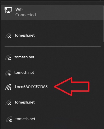
NOTE The Management Radio only is only on for a short period of time after boot. If the device cannot be found power cycle it by unplugging the device from the POE injector, wait 10 seconds, and plug it in again.
- Once the WiFi connection is establish, open the browser and visit
https://192.168.172.1/
Connect Using an Ethernet Cable
Device can be connected to using an Ethernet cable. This method requires the knowledge of the device's IP address. If the device has been previously configured, and the IP address is known, adjust the steps below accordingly. If the IP address is not known, a factory reset can be performed by pressing the reset button for 30 seconds. This will erase all settings on the device and set the default IP address of 192.168.1.20 again.
-
Plug a network cable into your computer and into the
Networkport of yourPOE injector -
Configure your laptop's network interface to
192.168.1.50. -
Open the browser and visit
https://192.168.1.20/
First Time Configuration
-
If there is a warning about a certificate, process anyway.
- Firefox: Press Advanced, then
Accept the Risk and continue - Chrome: Press Advanced, then
Proceed to xxx.xxx.xxx.xxx (unsafe)
- Firefox: Press Advanced, then
-
Select the country as
Canada -
Accept the user
EULA -
Click
Continue -
Choose Your username and password for the device. TCN Standard username is
tomesh
Configure Wireless
- Select the
Wirelessicon from the left menu
-
Enter the remote antennas SSID under
SSID -
Enter the
WPA2 PRESHARED KEY. TCN standard key istorontocommunitynetwork
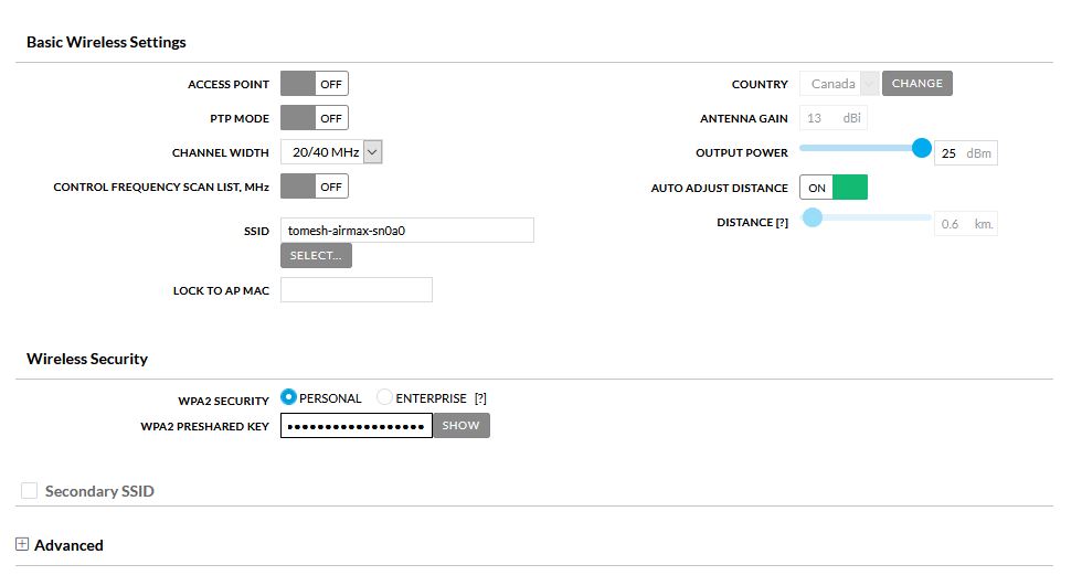
- Select
Save Changes
Configure Network
- Select the
Networkicon from the left menu
-
Set the
IP ADDRESSto the address assigned to your node -
Set the
NETMASKif needed. The default is255.255.255.0and used in most instances -
Enter the
GATEWAYassigned to your node. Usually same as yourIP ADDRESSbut ending in1 -
Set the DNS to
10.10.10.10 -
Set
IPV6address toSTATIC -
Enter
IPV6 ADDRESS,IPV6 NETAMSKandIPV6 GATEWAYto values provided.IPV6 NETAMSKis usually64
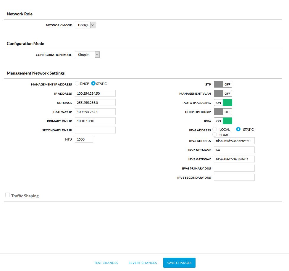
- Select
Save Changes
NOTE If you are using a network cable method of connecting to the device, you will need to change your IP address of your computer to the same network as you entered in the IP ADDRESS field. Simply select a different at the end. For example, if your assigned IP address is 100.64.10.55 set your computer to 100.65.10.200. You will have to use your browser to visit https://YOUR ASSIGNED IP for example https://100.64.10.55
Configure System
- Select the
Systemicon from the left menu
-
Set
DEVICE NAMEto your assigned node name -
Toggle
NTP CLIENTon -
Set
NTP SERVERto10.10.10.123 -
Set
TIMEZONEto(GMT -05.00) Eastern -
Toggle
READ-ONLY ACCOUNTon -
Set
READ-ONLY ACCOUNT NAMEtoubnt -
Click
CHANGEnext toChange Read Only User Passwordand set the password totomeshnet -
Fill out the location section.
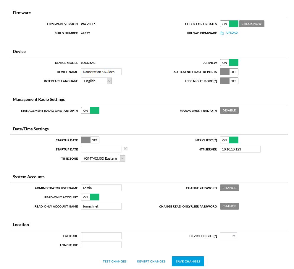
- Select
Save Changes
Operations
This section documents the operational aspects of the project.
Working Groups
We use GitHub Teams to manage membership of working groups and GitHub Projects to track task status on a public project board. These are our current working groups.
Communications and Community Engagement
Connect with people living and working in the areas served by the network(s), inform people regarding intentions and activities of the community network and engage them in dialogue with a view to mutual learning and collaboration in advancing the value of the network and related opportunities in the community.
| Spaces | |
|---|---|
| Meetings | Sunday 3 PM ET weekly (calendar iCal time poll) |
| Group Email | communications@tomesh.net |
| Chat | #communications:tomesh.net |
| Tasks | communications label |
| Membership | communications-and-community-engagement team |
Network Planning, Design and Operations
Plan, design, implement and maintain a well-functioning community network.
NOTE Regular meetings for this working group have been suspended. If there is interest in restarting a regular meetup time please let us know. Otherwise please direct any questions to the Email or Chat below
| Spaces | |
|---|---|
| Meetings | Regular meetings suspended until further notice (calendar iCal time poll) |
| Group Email | network@tomesh.net |
| Chat | #network:tomesh.net |
| Tasks | network label |
| Membership | network-planning-design-and-operations team |
Organizational and Program Governance
Develop administrative processes ensuring Toronto Mesh meets their commitments. Attend to assets and resources. Assist in integrating and synthesizing priorities, plans and schedules across different disciplines and activities to realize the mission of Toronto Mesh and the Toronto Community Network. Formalize relationships and agreements with and within the community network.
| Spaces | |
|---|---|
| Meetings | Monday 6 PM ET weekly (calendar iCal time poll) |
| Group Email | governance@tomesh.net |
| Chat | #governance:tomesh.net |
| Tasks | governance label |
| Membership | organizational-and-program-governance team |
Project Operations
Assist in organizing and removing barriers to the completion of work - including projects involving production of a funding application, design and deployment of network equipment, convening of meetings and workshops, etc.
| Spaces | |
|---|---|
| Meetings | Saturday 12 PM ET biweekly (calendar iCal time poll) |
| Group Email | operations@tomesh.net |
| Chat | #operations:tomesh.net |
| Tasks | operations label |
| Membership | project-operations team |
Get Involved
If you would like to join a working group and contribute to the Toronto Community Network, please email hello@tomesh.net to introduce yourself and indicate how you may like to participate.
In order to do our best work together we have a Code of Conduct.
Learning Group
Toronto Community Network has established a learning group for us to develop deeper understanding about projects related to our community network. This group meets regularly with the Organizational and Program Governance Working Group and you can find the meeting schedule on our calendar.
Reading List
Please use the notepad associated with each reading to indicate your name once you have completed the reading, and to put your reflections and questions anonymously, so we can decide which readings are ready to be discussed when we meet.
-
Development and management of collective network and cloud computing infrastructures (notepad, added 2020-08-29)
-
Community Networks Adapt to New Realities Under COVID: A DWeb Meetup Recap: Zenzeleni Networks (notepad, added 2020-08-29)
-
Constellations of Trust and Distrust in Internet Governance (notepad, added 2020-08-29)
-
The Tragedy of the Commons: How Elinor Ostrom Solved One of Life’s Greatest Dilemmas (notepad, added 2020-09-09)
-
Toronto Mesh Mission (added 2020-09-09)
Please add interesting articles here for the group to triage as future readings.
Legal
Toronto Mesh is a community organization established in 2016, stewarded by a group of individual contributors and supported by many value-aligned organizations. It is not an independent legal entity.
The Toronto Community Network is a project led by the Toronto Mesh community, and adopts a multi-stakeholder model to its project governance. Since neither Toronto Mesh or the Toronto Community Network has its own independent legal entity or bank accounts, it relies on trustees to provide fiscal administration capacity.
It is necessary for Toronto Mesh or the Toronto Community Network to engage into contractual agreements to work with many institutional collaborators. Depending on the nature of the collaboration, our Organizational and Program Governance Working Group will designate appropriate signatories to sign the agreement on behalf of Toronto Mesh or the Toronto Community Network on a case-by-case basis.
We understand that some organizations can only work with legally registered entities. If a contract must be made with a legal entity, we suggest a contract covering a specific project scope be made with one of our institutional collaborators. This way, you can indirectly work with the Toronto Community Network through this institutional collaborator. It is important to note that this contract will not bind Toronto Mesh or the Toronto Community Network as a whole, as collaborators do not individually represent the entire multi-stakeholder project.
Deciding Appropriate Signatories
TBD
Collaborators and Supporters
Licenses
Unless otherwise specified, Toronto Mesh code is licensed under GNU General Public License v3.0, content and documentation is licensed under Creative Commons Attribution-ShareAlike International 4.0 (CC BY-SA 4.0).
Finances
The purpose of this document is to describe the financial status and processes of the Toronto Community Network.
Introduction
The Toronto Community Network is a community project that current does not have its own independent legal entity or bank accounts, and relies on trustees to provide fiscal administration capacity. Aside from out-of-pocket spending from some of our members, our current financing comes from one single grant from the Internet Society administering through Free Geek Toronto.
Internet Society Grant for Supernodes (2020)
Internet Society was involved in discussions since ideation phases of the Toronto Community Network, and that is reflected in our Proposal to Establish a Toronto Community Network. This eventually led to a grant focused on deployment of high-capacity supernodes, which will establish an initial backbone from which to grow and sustain the Toronto Community Network. The initial supernodes span several major neighborhoods across the City of Toronto, selected and scheduled according to opportunities presented by the City of Toronto and our other collaborators through the Digital Canopy project.
The grant totals CAD 13,525 with the following budget:
- $10,428.00 for hardware, covering 4 supernode deployments
- $1,744.50 for operational expenses, including data centre colocation and internet transit
- $1,352.00 for grant administration, a 10% fee retained by our fiscal host Free Geek Toronto
The funds are payable to Free Geek Toronto in two installments, CAD 7,000 followed by CAD 6,525 upon completion of the milestone where 2 supernodes have been deployed. Toronto Mesh estimated a contribution of 1630 member hours of volunteer labour to the project.
Toronto Mesh and Free Geek Toronto are expected to deliver 3 reports by the following dates:
- 1st report: September 30, 2020
- 2nd report: November 15, 2020
- Final report: January 31, 2020 (summarizing all the work done until December 31, 2020)
Four core members of Toronto Mesh, who will serve as Administrators for this grant (explained below), have signed a Memorandum of Understanding (MoU) with Free Geek Toronto to formalize the fiscal hosting relationship. The full Internet Society Partnership Agreement and MoU are archived on our trusted drive, accessible only to core members due to confidentiality requirements from our partners.
Administration
The first of two installments in the amount of CAD 7,000 is paid to Free Geek Toronto in September of 2020, and the balance of CAD 6,300 (after 10% of administrative fees) is to be distributed for the project according to the budget set out in the grant proposal. We have two-levels of approvals for fund allocations:
-
Four members of Toronto Mesh involved in the grant application are selected as Administrators, and will approve allocations according to whether an expense fits with the spirit of the grant objectives and its proposed budget.
-
Free Geek Toronto will approve allocations according to the MoU, and they reserve the right to reject allocations that may put them in a position of legal liability due to violation of grant terms.
Expenses generally require pre-approval and receipt copies, archive and tracked in a spreadsheet on our trusted drive.
In the course of administering the grant, Administrators may draft request for proposals (RFPs) or delegate budgets to working groups to allocate as they deem necessary. For example, the Administrators may allocate a budget for training and request for member applications, or delegate a small budget for the Communications and Community Engagement working group to spend on an event as they see fit.
Hardware purchase makes up the bulk of the Internet Society grant budget. The Network Planning, Design and Operations working group will be responsible for making hardware procurement proposals using the following template, submitted as a pull request to operations/hardware-budgets:
# YYYY-MM-DD Hardware Budget for Toronto Community Network

## Purpose

_What is the hardware for? If this is related to a particular deployment and require approval by a specific date, please mention it here._

## Hardware List

_A list of all hardware items and the prices from specific vendors we plan to order from._

| Item   | Vendor   | Price | Currency | Quantity |
|:-------|:---------|------:|---------:|---------:|
| Item 1 | Vendor 1 |  0.00 |      CAD |        1 |
| Item 2 | Vendor 2 |  0.00 |      USD |        1 |

## Budget Requested

_The Administrators acknowledge that final reimbursement amounts may differ due to unforeseen costs like duties and exchange rates. This should be a best-effort estimate in Canadian Dollars._

| Budget    | Estimate (CAD) |
|:----------|---------------:|
| Hardware  |           0.00 |
| Shipping  |           0.00 |
| Duties    |           0.00 |
| Taxes     |           0.00 |
| **Total** |           0.00 |

## Sign-off

_The sign-off should include at least one experienced member in the Network working group._

Members of Network Planning, Design and Operations:
- Member 1
- Member 2

Grant Administrators:
- Administrator 1
- Administrator 2
- Administrator 3
- Administrator 4
For budget allocations above CAD 1,000, approval by 3 of 4 Administrators are needed. For amounts below that, only 2 of 4 approvals are necessary. The four Toronto Mesh Administrators are: @yurkowashere, @TimTor, @Shrinks99, and @benhylau.
Data
Toronto Community Network operates on principles of transparency, so most of our work is conducted in public digital spaces. The exception to this rule is when managing with personal information and sensitive information of our supporters and collaborators. This document describes our policy is finding the balance between working openly and restrictive access to certain information.
Document Management
We store our documents on two main platforms:
- Our Toronto Mesh GitHub hosts our main organizing repository in addition other repositories for more specific content, like data about our community network nodes.
- Our self-hosted Nextcloud drive contains two folders with different access levels:
- tomeshnet stores semi-public information. Any Toronto Mesh member gets full access.
- tomeshnet-trusted stores sensitive information, such as contact lists containing personal information and collaborator contracts that are explicitly asked to be kept private. Only active members with more than one year of contribution in our working groups have access to this folder, and access shall be revoked when the member is no longer actively involved with the project. In special cases, access may be allowed to specific members with less history as contributor on an as-needed basis, by approval of the Organizational and Program Governance Working Group.
Communication Policy
In general, we copy email and other communication to a working group address, for reasons of transparency and information redundancy. However, there are times when we seek to contain communication to a small group (for example, engaging new prospective collaborators, handling Code of Conduct violations). In these instances, we seek to keep groups to at least 3 members--one as lead, two copied, and have these roles listed on our contact sheet. Here is our communication policy in order of preference:
- Copied to appropriate working group.
- Copied to two others.
- Temporarily individual, but move to high redundancy as soon as possible.
Meeting Recording
In general, we do not record our meetings, but for workshops/interviews we have three options in order of preference:
- Public recorded session with unrecorded discussion in the end (for example, publish on "YouTube").
- Private recorded session with unrecorded discussion in the end (for example, archive to our member Nextcloud).
- Unrecorded session.
This is a choice of the facilitator/presenter of the session. Where possible, we will publish to a platform with closed captioning for accessibility.
In general, we have recorded sessions at our recorded BigBlueButton room, where a disclaimer is presented when someone enters the room.
Network Data
TBD
Managing Secrets
The purpose of this document is to provide information to contributors on how to store and view the Toronto Community Network's "secrets", such as passwords, keys, credentials, and other information kept private for security reasons.
Introduction
The Toronto Community Network uses Bitwarden to share and manage secrets across the organization. Bitwarden is a free and open-source password management service that stores sensitive information (such as website credentials) in an encrypted vault.
Bitwarden supports the following clients:
- Desktop (Linux/macOS/Windows)
- Web Browser (Chrome/Safari/Firefox/Vivaldi/Opera/Brave/Edge/Tor Browser)
- Mobile (Android/iPhone)
- Command Line (via NPM)
For more information about supported clients, see Bitwarden's download options.
Accessing Secrets
The Toronto Community Network is using the self-hosted version of Bitwarden, and can be accessed at https://pass.tomesh.net.
For secrets to be shared, they must exist within the Toronto Community Network organization.
When using the Bitwarden applications, please make sure to change the Server URL in the Bitwarden settings to the https://pass.tomesh.net.
Obtaining Access
Obtaining access to Bitwarden is a 4-step process.
-
Send an email to operations@tomesh.net with the following information:
- Your Name
- GitHub Handle
- Detailed description of your use case or requirement.
-
A member of our Project Operations team will invite you to Bitwarden.
- Bitwarden will send you an email from tomeshnet@gmail.com
- Please make sure to whitelist the email address.
-
Use the link in the invitation to create an account.
-
After registration, Bitwarden requires us to confirm your account. Upon confirmation, you will have access to the organization.
We recommend that you setup two-factor authentication on your account to increase the security of your account.
Access Control
When storing credentials, you must store them within the Toronto Community Network organization. Bitwarden organizes secrets in groups called Collections and within those Collections are four User Types: User, Manager, Admin, and Owner.
In order to maintain integrity of the Toronto Community Network operations, most users will be granted only User or Manager access. The Project Operations team will determine your access based on your use case or requirements.
Storing Secrets
All secrets must be attached to a Collection to facilitate access control. Please be sure to attach the secret to an existing Toronto Community Network Work Group. These collection names start with _OU.
Additional Collections may be created or utilized to classify the secret such as Social, Service Accounts, Website, and more.
When naming your credential, please use the following convention: System/Function - Identifier.
For example:
- A public SSH key may be named "Public Key - Contributor A"
- A GitHub deployment key may be named "GitHub - Deploy Key (docs.tomesh.net)"
- A shared login social media may be named "Twitter - tomeshnet"
When determining a password or passphrase, please use strong entropy to prevent unauthorized access. For more information, please see our Recommended Best Practices below.
All public keys and private keys must be saved as Secured Notes.
Please be mindful that secrets stored in this system can be accessed by any authorized contributor in the Toronto Community Network. While your connection to the system is secured via TLS, the secrets you choose to store in the group can be seen by others. Please refrain from using the system for storing any personal information.
For more information about managing items, please see Bitwarden's official documentation on Managing Items.
Data Backup
The VM that hosts the Bitwarden container is backed up on a weekly basis.
Administrators of the Toronto Community Network organization have the ability to export the entire vault to a JSON or CSV file.
As the export function provides secrets in clear-text, please secure or encrypt the file immediately.
Recommended Best Practices
The Government of Canada's Canadian Centre for Cyber Security provides recommendations for organizations to protect networks, systems, and information. By using these best practices, you can protect yourself and the integrity of the Toronto Community Network.